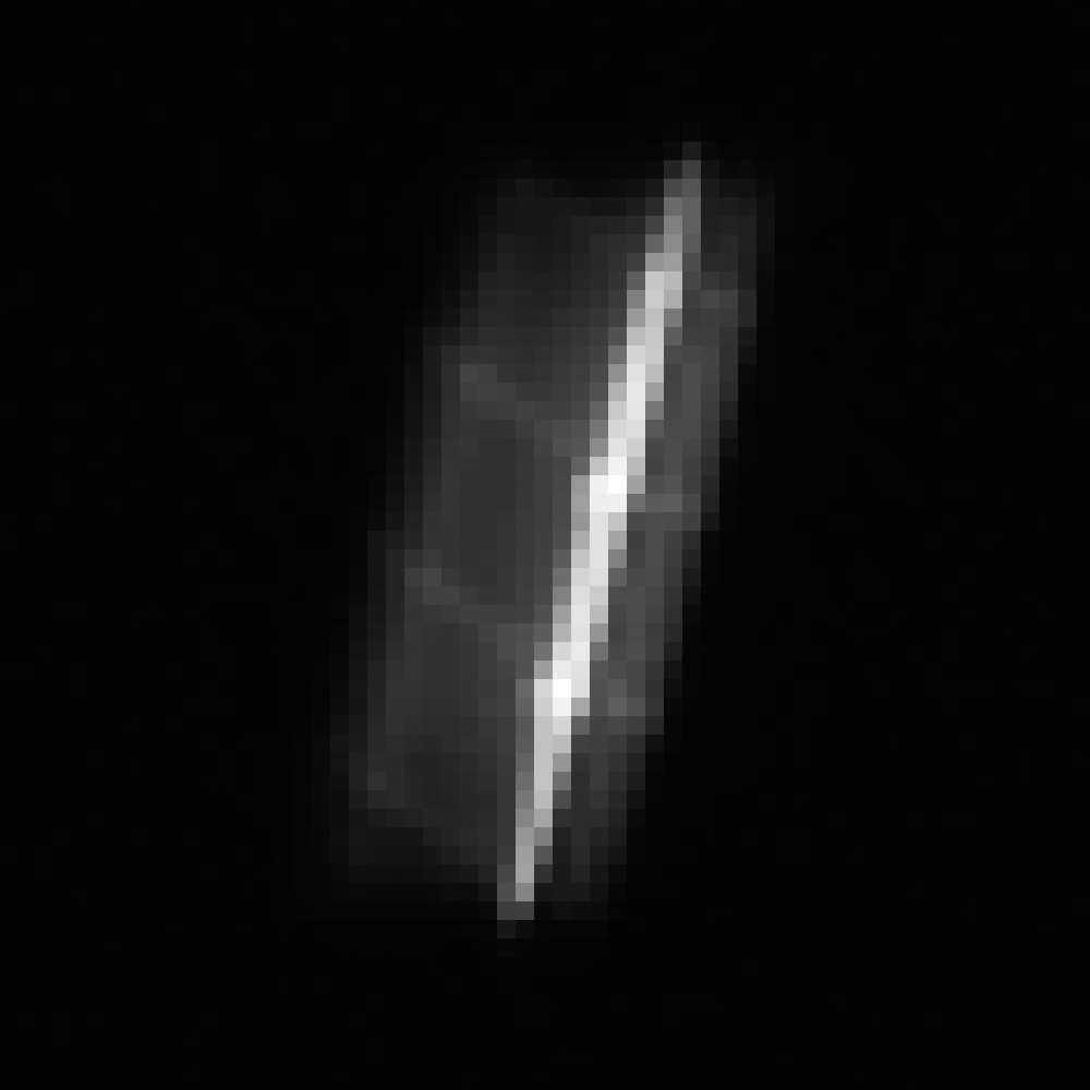
ShadowCam Captures the Lunar Reconnaissance Orbiter!

The Lunar Reconnaissance Orbiter Camera (LROC) team has had fun imaging other active spacecraft on the ground, roving around, and in orbit. This time it was the Lunar Reconnaissance Orbiter in the limelight. ShadowCam, LROC's sibling on the Korea Aerospace Research Institute (KARI) Danuri orbiter, took this picture as LRO passed just 18 km (11.2 miles) below. Note that there was no illuminated Moon beneath LRO at the time, thus the black background.
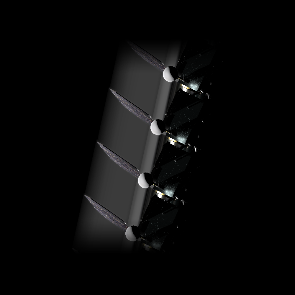
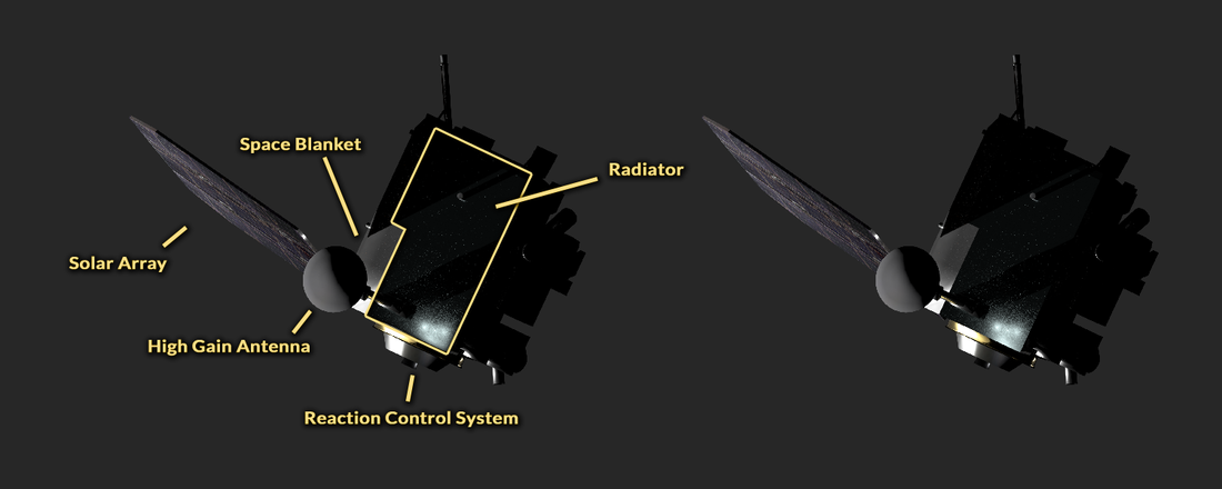
The NASA LRO mission operations team at Goddard Space Flight Center slewed LRO 20° away from the Sun to allow the radiator and back of the spacecraft to be brightly illuminated, ensuring that LRO would be clearly seen. With the ephemeris information provided by KARI and the LRO project, the relative positions and orientations of LRO, the LRO solar array, and Danuri were computed using the JPL NAIF SPICE Toolkit to create the view seen below.
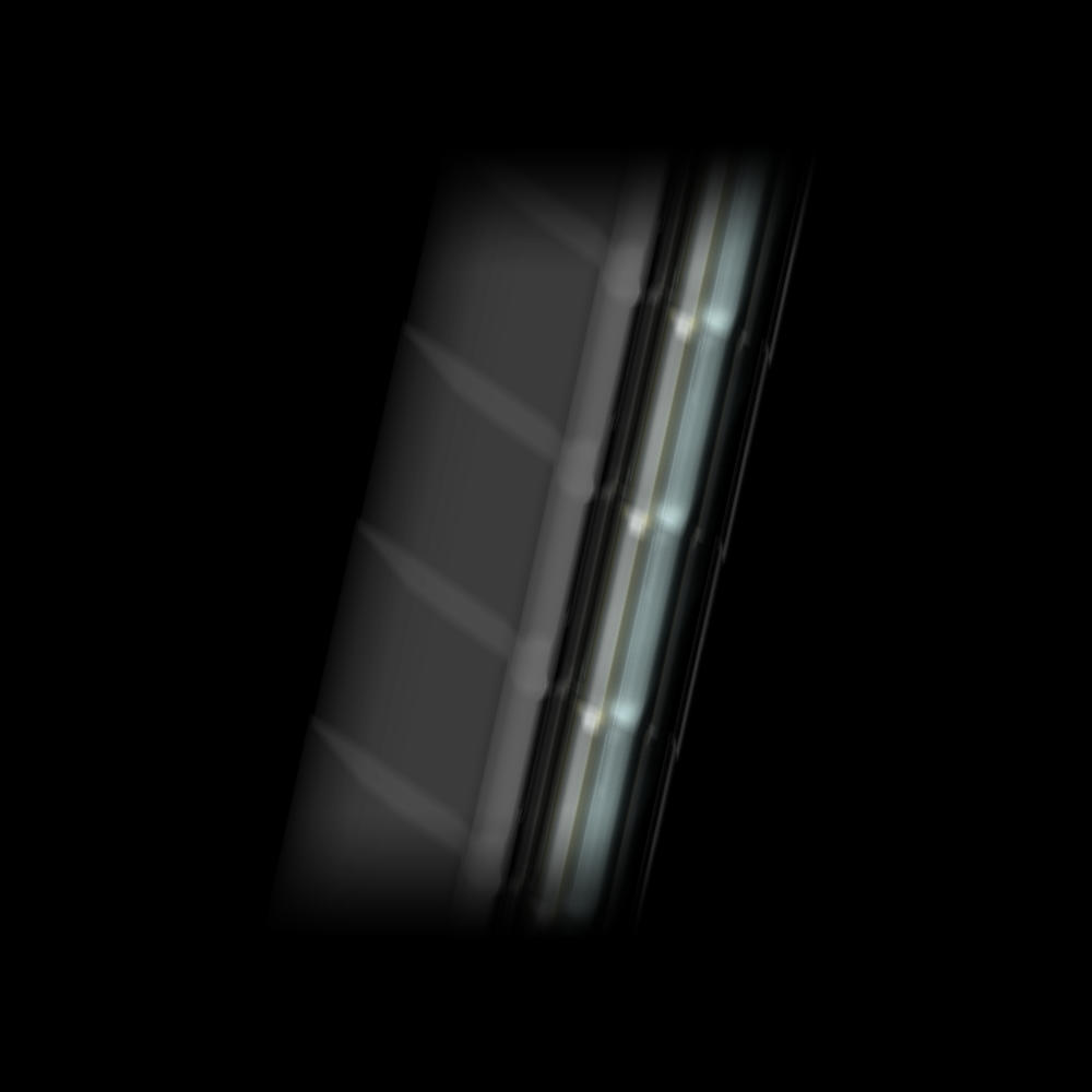
The simulated ShadowCam image was computed from an accurate CAD model of LRO with the correct orientation of the spacecraft and components relative to the Sun and Danuri. During one exposure time (0.001184 seconds), LRO was smeared in the motion of travel over 3 x 12 ShadowCam pixels. Each location of LRO is in one ShadowCam Pixel for only 0.000097 seconds, meaning that exposure was, in effect, set by the motion rather than the commanded exposure time. Think of long exposure images of cars on a highway, the car lights show up as lines.
The ShadowCam imaging sensor (chip) is similar to yet very different from those in an everyday digital camera. Typically a digital image (and film image) is exposed all at once. Push the shutter, and you take the picture.
With a Time Delay Integration (TDI) camera, the sensor is similar, except it is manufactured as a narrow rectangle of pixels (in this case, 32 rows and 3072 pixels) rather than something like 3000 rows by 4000 pixels. Another big difference, the image is built up over time as the scene moves past the camera. The TDI is commanded to expose at the same rate the scene moves past the camera; this rate is synchronized with the motion to avoid blurring. Thus, each of the 32 rows "sees" the same area as the scene moves past, then the rows are summed together to make one line. This design allows for effective short exposure times (minimize blurring) while maintaining a high signal usually associated with long exposure times.
The ShadowCam Time Delay Integration (TDI) sensor (Hamamatsu S10202-08-1) was commanded to cycle once every 0.001184 seconds, reading one line at a time (a line is 3072 pixels wide; each line is a sum of the 32 rows). During this process, each line is exposed 32 times. When timed correctly, row 1 of the detector passes over the target, and the light reflected from the target is measured and shifted to row 2; as row 2 passes over the target, light reflected from the target is measured and shifted to row 3; this process repeats for all 32 rows and then that 32 summed row is read-out as one line. But it is even more complicated than it seems; in this example, after row 1 passes its measurement to row 2, row 1 is now measuring reflected light on what will be the 2nd line of the image.
When this image was acquired, LRO passed underneath ShadowCam at a very high rate (>3000 meters per second), in the same direction as the TDI rows are shifted. In effect, the relative motions slow down LRO (but it is still way fast). This cadence results in LRO being doubly exposed for the instant in time that a line is read out (LRO appears in two of the 32 rows that summed to make one line). This double exposure occurred every 0.001184 seconds, and since LRO was traveling through the field of view for 0.003977 seconds, LRO was doubly exposed four times resulting in the multiple images seen in the final image. The dimmer regions between the doubly exposed rows are the singly exposed rows. Easy to understand - right?
Here is an alternate way to think of the process. Imagine that ShadowCam acquires a series of 32-row by 3072-pixel images one after another. Each image is shifted one row relative to the previous image. The images are then stacked on top of one another in stair-step fashion. The staircase is then "flattened" by summing all the values in the vertical direction (32 values). The summing process is one of the reasons for the very high sensitivity of Shadowcam, which allows it to image in shadowed areas. We were unsure of the optimal exposure time for imaging a closeby spacecraft traveling over 3000 meters per second. The trade-off was shorter exposure to reduce smear or longer exposure to ensure a high signal. In the end, we used the appropriate exposure time for imaging the Moon under normal ShadowCam conditions just in case a bit of Moon was visible.
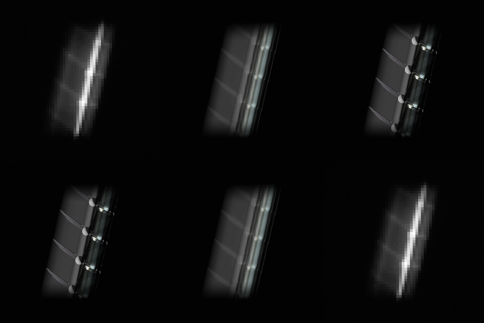
Comparing the rendered view of LRO to the actual ShadowCam image, it is possible to pick out some features of the spacecraft. The Reaction Control System (RCS), which maneuvers the spacecraft, is small in this view but is able to reflect more light than the flat radiator of LRO (see below). The LRO Solar Array (SA) is also visible, extending away from the spacecraft on the left, as well as either the High Gain Antenna (HGA) or a thermal blanket reflecting sunlight.
ShadowCam was built by Malin Space Science Systems (MSSS) in San Diego, CA.
Posted by Mark Robinson on 10 May 2023